RX-8 Fuel, Ignition and Starting Reference
Spark plugs, D585 coils, staged injectors, fuel pressure, KEMSO pump installation and starting checks.
Spark plugs
| Position | Plug | Gap | Torque |
|---|---|---|---|
| Leading | NGK RE8A-L standard; RE7A-L hotter factory option. Probable fitted set: RE7C-L. | 1.05–1.15 mm | 12.8–17.7 Nm |
| Trailing | NGK RE9B-T | 1.05–1.15 mm | 12.8–17.7 Nm |
Confirm the fitted leading marking from a removed plug or receipt before treating RE7C-L as a parts record. The lower NGK heat-range number is hotter; it does not create a stronger spark. Do not bend the iridium electrodes to adjust the gap.
Viewed from the left side of the engine, the upper ports are trailing and the lower ports are leading. The front rotor is nearest the radiator and the rear rotor nearest the bulkhead:
front     T/F     T/R     rear
          L/F     L/R
Label the four leads before removal and keep leading/trailing plugs separate. Wet fuel/oil suggests flooding or weak ignition; dry black carbon suggests fouling/rich short-running; blistering, glazed insulation or eroded electrodes suggests excess heat. Compare all four under the same recent operating conditions—one freshly flooded plug does not prove a mechanical fault.
Coils and leads
The factory system has four individually triggered coils with built-in igniters: L/F, T/F, L/R and T/R. PCM trigger outputs are 2AA, 2AD, 2Z and 2AC respectively. Coil terminal A is the trigger, B ground and C battery supply.
This car uses the Rotary Revs four-coil D585-format kit with its bracket, Magnecor leads and wiring adaptor. Mount the bracket rigidly, keep its earth and engine/body earths clean, seat every adaptor latch, and protect the coils/leads from exhaust heat. Route each lead by position—not by whichever cable reaches.
For a misfire:
- Read stored and pending DTCs before clearing anything.
- Check battery voltage at the coil supply while cranking and running; voltage drop matters more than an unloaded reading.
- Measure earth voltage drop between coil bracket/ground and battery negative under load.
- Inspect connector pin fit, heat damage and arcing tracks. Factory plug-lead resistance reference is 1–4 kΩ; plug resistance is 3–7.5 kΩ.
- Inspect the plug, then substitute one known-good coil/lead while keeping the labelled route.
Unburnt fuel can overheat the catalyst quickly, so do not continue a sustained misfire. D585 coils are not a licence to invent dwell: use the supplier’s documented adaptor/tune strategy for the actual coil electronics.
Six-injector arrangement
| Stage | Front rotor | Rear rotor | Use |
|---|---|---|---|
| Primary 1 | FP1 | RP1 | Low fuel demand |
| Secondary | FS | RS | Added as demand rises |
| Primary 2 | FP2 | RP2 | High-power engine, higher demand |
Factory resistance is approximately 13.8 Ω at 20 °C. Standard OEM-flow injectors suit the unmodified ECU calibration because the commanded pulse width and staged transitions assume the original flow characteristics; replacing all six with OEM units does not establish that they are flow-matched.
Relieve pressure, disconnect the battery and label every connector before removing the rails. Pull each rail squarely so an injector is not side-loaded. Replace upper O-rings and lower grommets/seals, lubricate them with clean fuel or the manual-approved lubricant, and never push a dry O-ring into the rail. After refitting, command the pump or crank with ignition disabled, inspect every injector/rail joint, then repeat the leak check with the engine running.
Rich trims, fuel smell, difficult hot starts and a rapid residual-pressure loss can indicate leakage. Lean trims or a weak high-load rotor can indicate restriction or staging/wiring faults; compare commanded stage, injector resistance and pressure before replacing parts.
Fuel pressure and pump control
Connect a suitable tee and pressure gauge at the engine-bay quick-release fuel-feed connector. Use the correct fuel-line SST/adaptors and contain released fuel.
| Test | Mazda reference |
|---|---|
| Running fuel-line pressure | 375–450 kPa / 3.75–4.50 bar / 54.4–65.2 psi |
| Residual after five minutes | At least 200 kPa / 2.0 bar / 29 psi |
| Fuel-pump resistor at 20 °C | 0.304–0.336 Ω |
| Low-state pump voltage, Mazda test condition | 3.76–5.28 V |
The fuel-pump and fuel-pump-speed-control relays are in the engine-compartment main fuse/relay box. At low demand the speed relay is off and pump current passes through the engine-compartment resistor. At high demand or cranking the PCM energises the speed relay, bypassing the resistor so the pump sees battery supply. Listen for the pump-frequency change while commanding FPRR with a capable scan tool.
KEMSO 10910 installation
| Published item | KEMSO value |
|---|---|
| SKU | 10910 |
| Nominal flow | 340 L/h |
| Flow condition | 43 psi at 13.5 V |
| Published pressure range | 43–90 psi |
| Body diameter | Approximately 38 mm |
The 340 L/h figure is a bench point, not in-car delivery at all voltage and pressure states. The RX-8 deliberately operates the pump at reduced voltage during low demand, so validate pressure in both relay states.
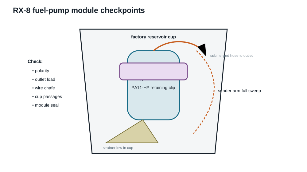
- Record baseline running/residual pressure and fuel-level indication. Relieve pressure, disconnect the battery, ventilate the area and remove the rear-seat pump service cover.
- Clean outside the module before opening it. Mark the lock-ring/module orientation and photograph the sender arm, cup, strainer and wiring.
- Lift the module without bending the sender arm. Drain it into an approved container and compare the KEMSO body/outlet/polarity with the original pump.
- Fit the strainer at the bottom of the reservoir cup in the same low orientation, clear of the cup wall and sender sweep.
- Use only hose rated for continuous submerged in-tank fuel service and fuel-injection clamps. General external fuel hose can delaminate when its outer surface is submerged.
- Confirm connector polarity, terminal retention and insulation. Secure the pump without point-loading its body or outlet and ensure the hose cannot kink as the module closes.
- Move the sender through its full travel and check clearance to the pump, PA11 clip, strainer, wires and hose. Verify the reservoir-cup fill/jet-pump passages remain unobstructed.
- Fit a sound module seal, return the module to its orientation marks and tighten the lock ring by the Mazda method. Reconnect, command the pump and check for vapour/liquid leaks before refitting the cover.
- Recheck fuel-level indication, running pressure, five-minute residual pressure, connector temperature and pressure in both low/high pump states.
PA11 retaining clip
The custom MJF clip locates the 38 mm KEMSO body in the factory module. It is printed in PA11-HP; final CAD dimensions remain in the private build record.
A prototype clip was left immersed in fuel for three weeks. After removal, it retained its apparent structural stiffness and no visible residue was observed in the fuel. This was a useful preliminary compatibility check, but it was not a complete long-term qualification test.
That observation did not measure swelling, mass change, creep or lifetime. On service, inspect contact stress, cracks, softening, wire/outlet damage and sender/cup clearance. A future check should add dimensional and pull testing, vibration/shock exposure and longer-term inspection in the identified pump fuel.
Starter and cranking
The original manual-transmission starter is a 1.4 kW coaxial-reduction unit; Mazda’s no-load reference is no more than 90 A at 11 V. This car has an uprated replacement, but its exact model, rated power and tooth count are not recorded, so it is not described as a specific 2.0 kW/13-tooth unit.
For slow or hot cranking:
- Measure rested battery voltage, voltage at the battery during cranking and actual rotary cranking rpm.
- Measure positive drop from battery positive to starter B+ while cranking, then earth drop from starter housing/engine to battery negative. A poor cable or earth can leave a new starter slow.
- Check terminal tightness, engine/body earth straps and heat damage near the exhaust.
- Compare hot and cold rpm/current. High current with low rpm points toward starter/mechanical drag; low current with excessive voltage drop points toward the supply path.
- Interpret hot-start behaviour alongside compression, flooding and fuel residual pressure rather than treating starter speed as the only cause.
Cranking rpm directly affects rotary compression pressure, which is why every compression test must record it.