RX-8 Rotary Compression Testing
Mazda limits, test procedure, waveform timing and a compact result sheet for the two-rotor 13B-MSP.
Quick limits
| Measurement at 250 rpm | Limit |
|---|---|
| Standard | 830 kPa / 8.30 bar / 120.4 psi |
| Minimum | 680 kPa / 6.80 bar / 98.6 psi |
| Maximum spread across one rotor | 150 kPa / 1.50 bar / 21.8 psi |
| Maximum front-to-rear difference | 100 kPa / 1.00 bar / 14.5 psi |
Do not compare an uncorrected low-speed reading directly with the 250 rpm limits. A useful report retains all three events, actual cranking speed, raw values, corrected values and test conditions.
Test procedure
- Fully charge and load-test the battery. Warm the engine, shut it down and wait approximately ten minutes for exhaust temperature to fall.
- Remove one leading or trailing plug from each rotor. A Mazda rotary tester may be fitted to either plug hole; keep the unused holes sealed and the removed leads labelled.
- Disconnect the eccentric-shaft position-sensor connector. Mazda uses this step to inhibit both injection and ignition.
- Fit the rotary compression transducer to the selected front-rotor plug hole. Do not use a conventional one-way-valve piston-engine gauge: it retains only the highest event.
- Hold the accelerator fully open and crank for 5–10 seconds, long enough to obtain stable repeating events.
- Record front A/B/C peak pressure and the actual rpm. Repeat once if timing or amplitude is unstable.
- Move the transducer to the rear rotor, keeping battery state and test temperature as consistent as possible, and repeat.
- Correct each result to 250 rpm with the Mazda correction graph or a tester implementation validated against it. Do not apply an invented universal linear factor.
- Compare the absolute corrected pressure, within-rotor spread, front-to-rear difference and repeatability.
- Refit the plugs at 12.8–17.7 Nm, reconnect the eccentric-shaft sensor and restore the leads to their labelled positions.
Waveform explanation
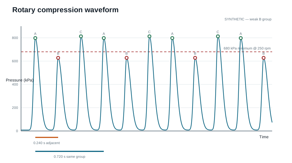
The graph is synthetic—not a measurement from this car. A, B and C are the three repeating waveform groups. They must not be assigned to physical rotor faces unless an external phase reference identifies crank/rotor position.
For a time interval in seconds:
RPM = 60 / adjacent peak interval
RPM = 180 / same-face interval
At 250 rpm, adjacent groups are 0.240 s apart and the next occurrence of the same group is 0.720 s later. A consistently weak group suggests a local sealing problem; three similarly low groups more often point toward general wear, low cranking speed, temperature or test setup. A single noisy sample is not a diagnosis—repeat it under matched conditions.
Result sheet
| Rotor | Raw rpm | A raw | B raw | C raw | A @ 250 | B @ 250 | C @ 250 | Spread | Notes |
|---|---|---|---|---|---|---|---|---|---|
| Front | __ | __ | __ | __ | __ | __ | __ | __ | __ |
| Rear | __ | __ | __ | __ | __ | __ | __ | __ | __ |
Record units, coolant temperature, battery voltage, tester identity and date with the table. Compare the two rotor means only after all values have been corrected consistently.
Devlin Rotary tester
The Devlin Rotary tester is a functional prototype under development. It uses 0–300 psi pressure transducers, records pressure through time, finds valid peaks, calculates cranking rpm, groups the three repeating events, reports kPa/bar/psi and corrects results to 250 rpm. The public notebook deliberately omits its full schematic, BOM, PCB, filter constants and firmware while the design is being validated.