RX-8 Cooling System: Hose Routing, Drain/Fill and Fan Control
Coolant routing, hose references, draining, filling, bleeding and fan control for the Series 1 high-power Mazda RX-8.
- System layout
- Coolant-hose register
- Draining
- Refilling and bleeding
- Fan logic and checks
- Manual fan control
Quick reference
| Item | Value |
|---|---|
| Total capacity | Approximately 9.8 L |
| Thermostat | Starts opening 80–84 °C; fully open at 95 °C; lift at least 8.5 mm |
| Cap pressure | 73.3–103.3 kPa |
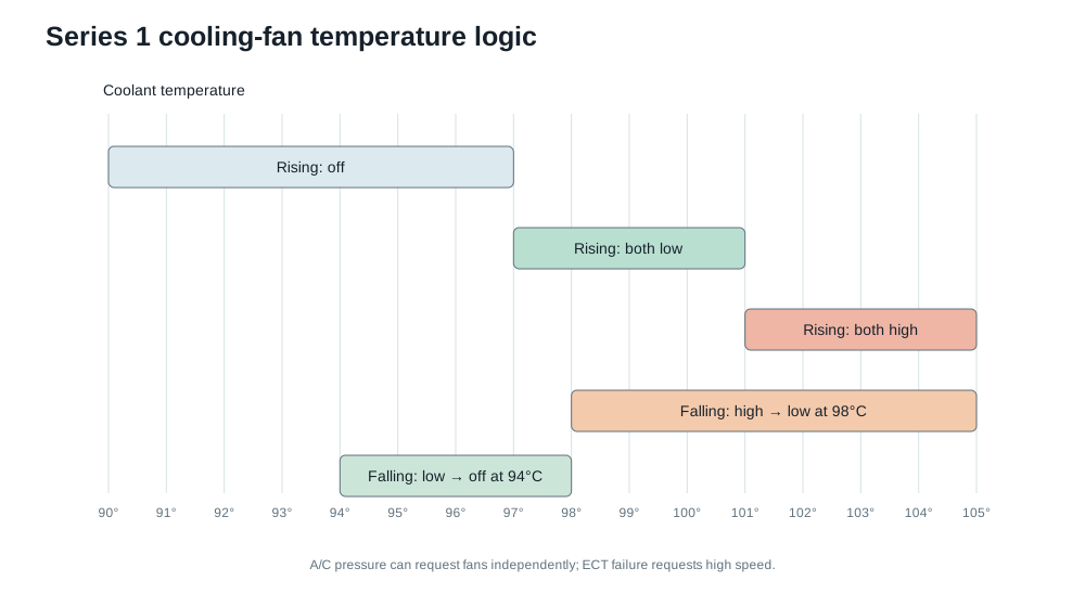
| Fan low | On at 97 °C; off below 94 °C |
| Fan high | On at 101 °C; returns to low below 98 °C |
System layout
The pump sends coolant through the engine housings. With the thermostat closed, flow recirculates through the bypass while the heater and throttle-body branches remain in circuit. As the thermostat opens, the main flow runs through the upper joining pipe to the radiator and returns through the lower hose to the pump/thermostat inlet. Small bleed lines continuously return air and coolant to the pressurised expansion/degas tank.
Coolant-hose register
Hose families are useful ordering cross-references, not guarantees across production breaks. The blank dimensions are intentionally left for measurement from the RHD car.
| ID | From | To | Function | OEM reference | ID A | ID B | Length | Notes |
|---|---|---|---|---|---|---|---|---|
| H01 | Lower radiator outlet | Thermostat/water-pump inlet | Cooled return | N3H1-15-185 family | __ | __ | __ | Large lower radiator hose |
| H02 | Upper radiator outlet | Front metal joining pipe | Hot radiator feed | N3H1-15-186 family | __ | __ | __ | Large upper/front hose |
| H03 | Rear metal joining pipe | Rear engine water connection | Hot engine outlet | N3H2-15-186 family | __ | __ | __ | Rear joining hose |
| H04 | Radiator bleed/degas port | Expansion tank | Air/bleed return | N3H1-15-184 family | __ | __ | __ | Small top hose |
| H05 | Thermostat housing | Expansion tank upper port | Degas/bypass | N3H1-15-380 family | __ | __ | __ | Small moulded hose |
| H06 | Expansion tank lower outlet | Thermostat housing | Tank feed/return | N3H1-15-381 family | __ | __ | __ | Lower tank hose |
| H07 | Thermostat/water connection | Throttle body | Throttle warming feed | N3H1-13-692 family | __ | __ | __ | N3H1-13-692C supersedes A/B |
| H08 | Throttle body | Rear water connection | Throttle warming return | N3H1-13-691 family | __ | __ | __ | Confirm routing before removal |
| H09 | Rear engine housing | RHD heater feed | Cabin-heater feed | — | __ | __ | __ | UK RHD part number to confirm |
| H10 | Heater feed/intermediate joint | Heater matrix | Cabin-heater feed link | — | __ | __ | __ | UK RHD part number to confirm |
| H11 | Heater matrix/firewall | Engine return | Cabin-heater return | — | __ | __ | __ | UK RHD part number to confirm |
Some aftermarket “18-piece coolant” kits count seven breather, intake or ancillary hoses alongside these eleven coolant routes. Classify each hose by its endpoints before fitting it; do not connect a similarly sized vacuum or breather hose into the cooling circuit. Left-hand-drive heater references such as FE01-61-211/-213 do not establish the UK RHD hose shape.
Draining the system
There is no separate engine-block drain in Mazda’s Series 1 coolant-replacement procedure. A radiator-drain service therefore leaves coolant in the heater matrix, rear housing, thermostat/bypass cavity, upper joining pipe and throttle-body loop.
- Let the engine cool completely and remove the centre splash shield/undertray for access.
- Slowly remove the expansion-tank pressure cap.
- Put a wide drain tray beneath the radiator’s lower tank and open the plastic radiator drain plug.
- Let the expansion tank empty through the connected lower hose. Squeeze the main hoses gently to move retained pockets; do not use compressed air.
- For a more complete drain, disconnect H01 at the lowest point after the radiator has stopped flowing. Catch the additional coolant rather than assuming the system is empty.
- Inspect the plastic drain plug and its seal, then refit it hand-snug. Mazda does not publish a torque or a separate sealing-washer instruction for this plastic plug.
- Reconnect H01 with its clamp returned behind the hose bead and refit the undertray after leak checks.
A normal radiator/lower-hose drain often recovers roughly 7–8 L, not the full 9.8 L. Measure what came out so the refill amount and antifreeze concentration make sense.
Refilling and bleeding
Use an ethylene-glycol coolant mixed with demineralised water for the required freeze protection. If the cap or filler neck carries the FL22 mark, replenish with premixed FL22; do not dilute it.
- Check that the drain plug and H01 are secure. Set the cabin heat to hot; the electronic heater does not rely on this to open a simple coolant valve, but heat output is a useful circulation check.
- Fill the expansion tank slowly to F, pausing to squeeze H01, H02 and the accessible heater hoses. Let bubbles return before adding more.
- Fit the pressure cap. Start the engine, inspect every disturbed joint and let it idle until warm.
- Hold approximately 2,500 rpm for five minutes, then 3,000 rpm for five minutes, then return to idle. Repeat these speed stages several times as Mazda specifies while watching temperature and confirming steady cabin heat.
- Confirm the upper radiator hose becomes hot as the thermostat opens. Continue until temperature is stable and the cooling fans cycle; stop immediately for a rapid temperature rise or loss of cabin heat.
- Shut down and let the engine cool completely. Never open the pressurised tank hot.
- Top the cold level to F, repeat the heat/cool cycle if the level dropped, then recheck after the first full drive and again the next morning.
Intermittent heater output points to air at the heater matrix/firewall hoses. A sudden level drop when the thermostat opens usually comes from the rear housing or bypass region. Persistent gurgling can remain in the upper joining pipe, throttle-body loop or the small bleed hoses; check those hoses for kinks before repeating the cycle.
Fan logic and checks
| Coolant/command condition | Relays | Behaviour |
|---|---|---|
| Up to 96 °C, no A/C request | None | Both fans off |
| 97–100 °C rising | No. 1 | Both fans low speed |
| 101 °C or above rising | Nos. 1, 2 and 3 | Both fans high speed |
| Cooling from high | High remains to 98 °C; low remains to 94 °C | Hysteresis prevents rapid switching |
| A/C request | PCM selects low/high from refrigerant pressure | Temperature is not the only input |
| ECT circuit fault | Fail-safe request | Both fans high speed |
At 12 V, Mazda’s motor-current references are 8.9–11.9 A for fan No. 1 and 4–7 A for fan No. 2. If neither fan runs, check the main fan fuses, relay No. 1, both motor connectors and grounds. If low is missing but high works, concentrate on relay No. 1 and the series/low-speed path. If only one fan runs, test that motor and its branch before blaming the PCM.
Manual fan control
The Series 1 fan relays can also be manually requested while retaining normal PCM control. A separate wiring note covers:
- Manual low-speed operation
- Manual high-speed operation
- Two-switch and AUTO/LOW/HIGH arrangements
- PCM
5Xand5ADcontrol - Potential
P0480/P0481monitoring consequences
Manual cooling fan switch wiring
References
- Mazda cooling-system flow
- Mazda cooling-fan control
- Mazda fan relay control circuit
- Mazda RX-8 Series 1 Workshop Manual — coolant replacement and hose location sections.