RX-8 Jacking Points, Wheels, Brakes and Alignment
Jack and stand locations, wheel data, brake limits and alignment settings for RX-8.
Jacking and support points
Front central jack: the reinforced centre of the front suspension crossmember. Put the pad beneath the flat central member, behind the plastic undertray—not beneath the aluminium sump or the thin undertray.
Rear central jack: the solid centre of the differential casing. Keep the cup clear of the rear cover, drain plug, cooling fins, propshaft flange and PPF.
Axle stands: the four reinforced sill support areas immediately inboard of the pinch welds, marked by the sill location notches. A slotted rubber pad protects the folded seam. Raise centrally, then lower onto the matching left/right pair.
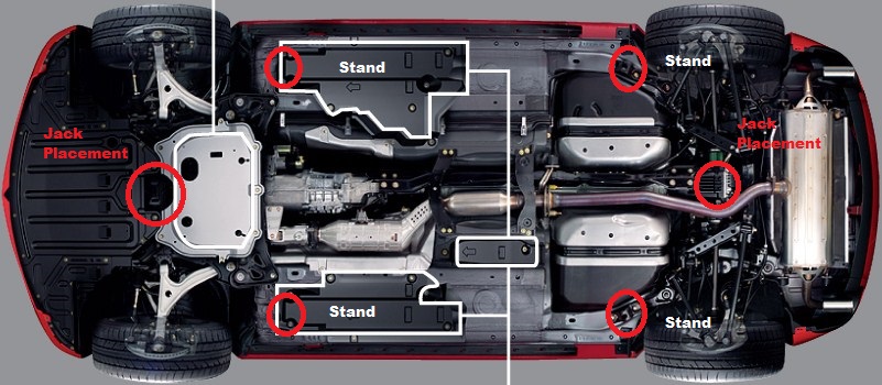
Never work beneath the car while it is supported only by a jack. Do not load the sump, gearbox casing, PPF, propshaft, differential rear cover, floorpan or thin sheet-metal braces.
Wheels and tyres
| Item | Value |
|---|---|
| Standard wheel | 18 × 8JJ, ET50 |
| Stud pattern | 5 × 114.3 mm |
| Standard/fitted tyre | 225/45R18 91W; Michelin Pilot Sport 5 |
| Cold pressure | 220 kPa / 2.2 bar / 32 psi, front and rear |
| Wheel nuts | 88–118 Nm, tightened diagonally |
| Nominal tyre diameter | 659.7 mm |
The calculated diameter is not the loaded rolling radius used by a tyre under load. Clean the hub and wheel seating faces, check for corrosion or cracks, and confirm the wheel sits flush before tightening. Follow the sidewall arrows on directional tyres; asymmetric tyres must keep outside facing out. Directional tyres can only move front-to-rear on the same side unless they are remounted.
Brakes
| Item | Front, high-power | Rear |
|---|---|---|
| Disc diameter | 323 mm | 302 mm |
| Disc thickness, new | 24 mm | 18 mm |
| Minimum thickness | 22 mm | 16 mm |
| Minimum after on-car machining | 22.8 mm | 16.8 mm |
| Maximum runout, measured 10 mm from edge | 0.05 mm | 0.05 mm |
| Maximum thickness variation | 0.015 mm | 0.015 mm |
| Minimum pad lining | 2 mm | 2 mm |
| Carrier/bracket bolts | 78–102 Nm | 49–69 Nm |
| Slider bolts | 22–31 Nm | 22–31 Nm |
Use DOT 3 brake fluid meeting SAE J1703/FMVSS 116. Mazda’s bleeding instruction is furthest caliper from the master cylinder to nearest; on this UK RHD car that is left rear, right rear, left front, right front. If the master cylinder has been emptied or removed, bleed its ports first and repeat them after the calipers. Bleed-screw torque is 6.9–9.8 Nm.
The rear piston incorporates the parking-brake adjuster. Wind it clockwise into the caliper with the correct tool; do not force it straight back with a clamp. Align the piston recess with the pad locating pin. After assembly, pump the service-brake pedal until firm before operating or adjusting the handbrake. Factory lever travel is 1–3 notches under a 98 N pull measured 50 mm from the lever end.
Alignment conditions
Check pressures first. Mazda specifies a full fuel tank, correct engine oil and coolant, jack/tools in their stowed positions, no extra load, and a settled suspension at normal ride height. Measure the fender-centre height vertically through each wheel centre because the nominal camber and caster depend on ride height. Left-to-right camber and caster difference must remain within 1°.
Toe
| Axle | Total toe at tyre | Total angle | At inner rim: standard / sport |
|---|---|---|---|
| Front | 2 ± 4 mm | 0°11′ ± 21′ | 1.2 ± 2.5 / 1.4 ± 2.8 mm |
| Rear | 3 ± 4 mm | 0°16′ ± 20′ | 1.9 ± 2.5 / 2.1 ± 2.8 mm |
Target zero thrust angle by making rear individual toe equal about the vehicle centreline; Mazda’s Series 1 table does not give a separate thrust-angle tolerance.
Standard-suspension camber and caster
| Front fender height | Front camber | Rear fender height | Front caster | Rear camber |
|---|---|---|---|---|
| 367–376 mm | −0°33′ | 361–370 mm | 6°31′ | −1°30′ |
| 377–386 mm | −0°13′ | 371–380 mm | 6°18′ | −1°12′ |
| 387–396 mm | +0°04′ | 381–390 mm | 6°06′ | −0°56′ |
| 397–406 mm | +0°20′ | 391–400 mm | 5°53′ | −0°43′ |
| 407–416 mm | +0°33′ | 401–410 mm | 5°40′ | −0°33′ |
Camber/caster tolerance is ±1° around the height-dependent nominal value.
Sport-suspension camber and caster
| Front fender height | Front camber | Rear fender height | Front caster | Rear camber |
|---|---|---|---|---|
| 361–370 mm | −0°45′ | 354–363 mm | 6°41′ | −1°44′ |
| 371–380 mm | −0°25′ | 364–373 mm | 6°28′ | −1°24′ |
| 381–390 mm | −0°06′ | 374–383 mm | 6°16′ | −1°07′ |
| 391–400 mm | +0°11′ | 384–393 mm | 6°03′ | −0°52′ |
| 401–410 mm | +0°26′ | 394–403 mm | 5°50′ | −0°40′ |
Front camber/caster eccentric nuts and rear camber eccentric nuts are 117.7–137.3 Nm. Rear toe-cam nuts are 70–95 Nm; front tie-rod locknuts are 37–49 Nm. Final-tighten fasteners passing through bonded-rubber bushes at normal ride height.