MP1 — Modular Breathing Apparatus Stowage
MP1 — Modular Breathing Apparatus (BA) Stowage
A universal, modular stowage system for SCBA/BA kits developed alongside Emergency One (E1).
MP1 replaces bespoke, one-off fixtures with a configurable assembly that securely holds single cylinders and twin-pack systems while meeting cab ergonomics and crash-load requirements.
Project Brief
E1 needed a BA stowage solution that could:
- Fit the existing cab integration space with no rework to the vehicle structure
- Support different BA set formats (single + twin pack) without unique brackets per customer
- Allow fast, gloved operation in low visibility (PPE constraints)
- Meet a 10 g crash requirement for a ~20 kg cylinder equivalent load
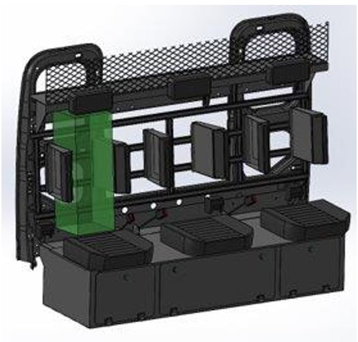
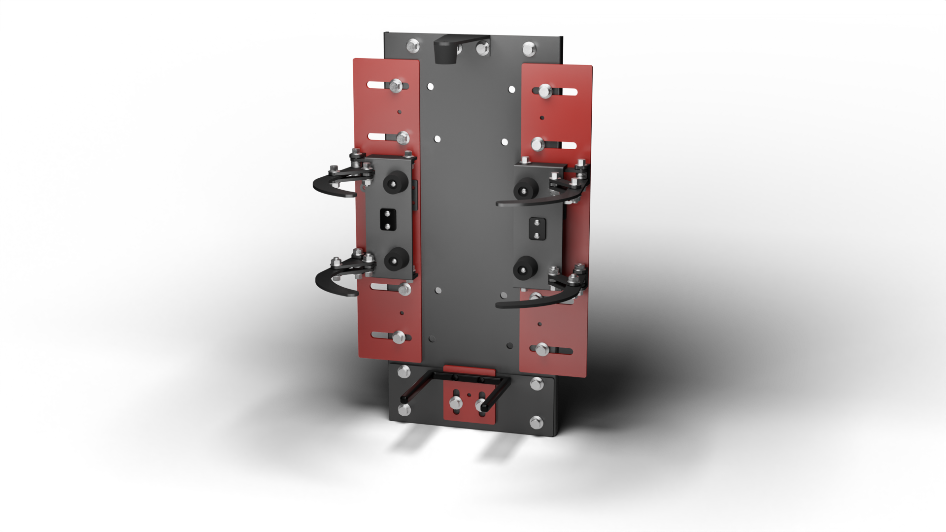
Design Envelope & Constraints
Cab integration envelope (drop-in compatible): 256 mm (W) × 735 mm (H) × 275 mm (D)
This envelope was taken directly from E1 cab CAD (“green zone”) to ensure installation without cab redesign. The same envelope logic also makes the architecture transferable to rear lockers.
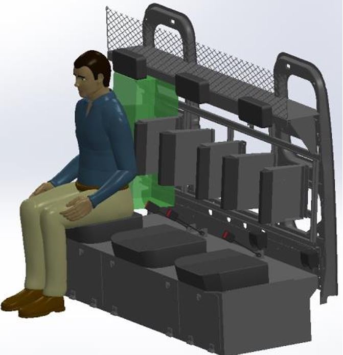
Operational constraints that drove the design:
- Shallow depth is the controlling constraint (cab comfort + clearance around seat and controls)
- Users operate in full PPE → reduced dexterity + limited visibility
- BA must remain accessible for rapid egress and valve checks while docked
User Interaction: What the Firefighter Actually Does
The system is designed around a simple, push-to-stow motion:
- Push BA into the dock (gross motor action)
- The push plate retracts, guiding the cylinder(s) into position
- Curved side arms wrap and clamp the cylinder(s)
- A rotary latch locks the mechanism
- A seat-integrated pull handle releases the latch for rapid removal
Key UX choices:
- Hands-free clamping: no fiddly straps or clips
- Red-coded touchpoints: handle + actuation parts are visually obvious in dark cabs
- Manual override preserved: direct access to latch maintained per safety requirements
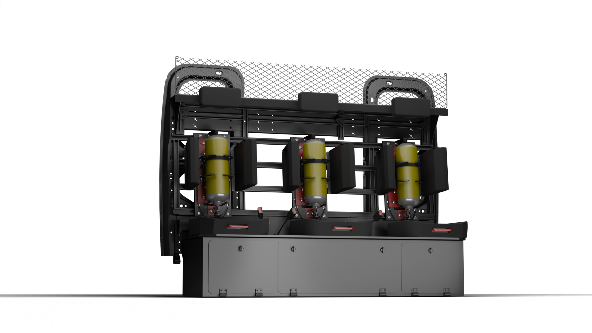
System Architecture
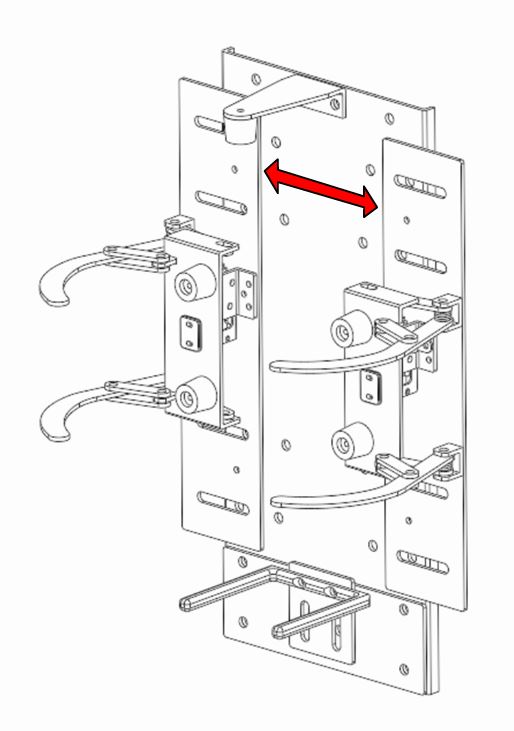
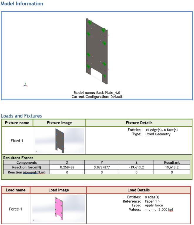
1) Structural Spine: Back Plate + Sliding Panels
- Back plate bolts into E1’s seat frame (primary load path)
- Two sliding front panels set the effective clamping width
→ enabling one architecture to accept single or twin-pack kits without bespoke fixtures
Why sliding panels matter: instead of redesigning the whole cradle per BA format, the same backbone adapts via a controlled adjustment feature (and can be pinned via pilot holes to prevent drift).
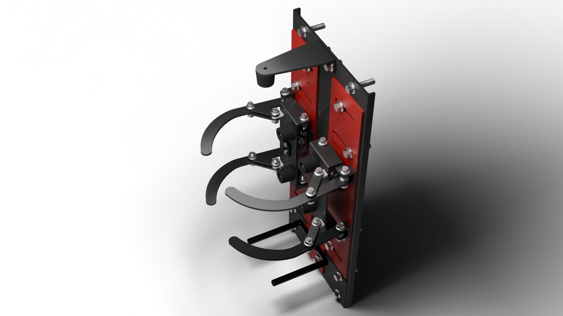
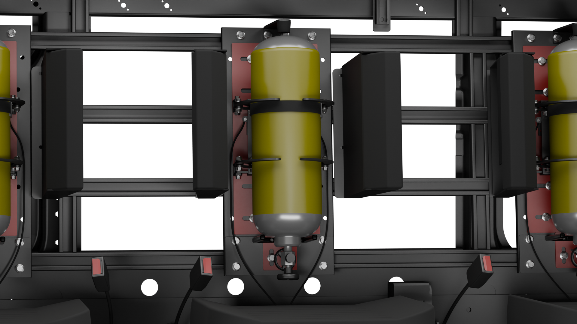
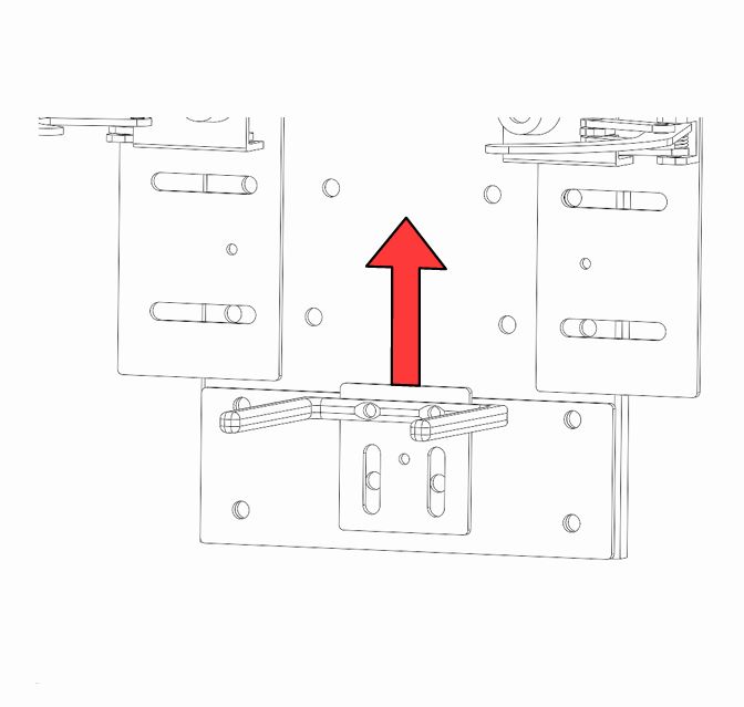
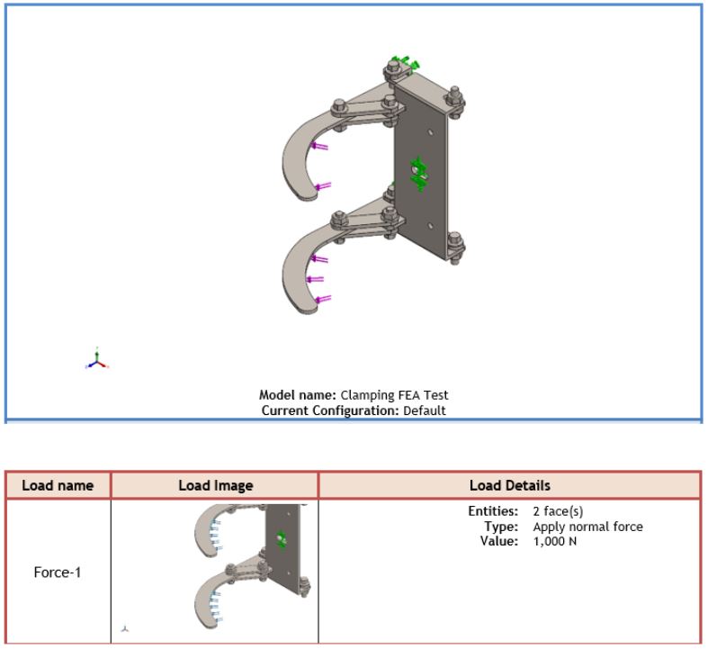
2) Clamping Mechanism: Push Plate + Arms + Springs
- The push plate acts as the “input surface” during stowage
- A pair of curved arms clamp the cylinder(s) from the sides
- Torsion springs reset the system to an open state after release
(so it always “presents” ready-to-stow)
Design intent: clamp loads are reacted into the back plate and seat frame, rather than into plastics/trim. 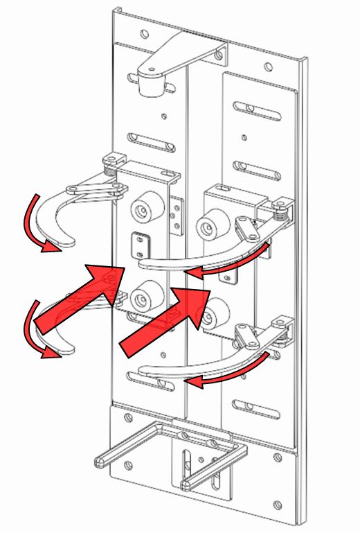
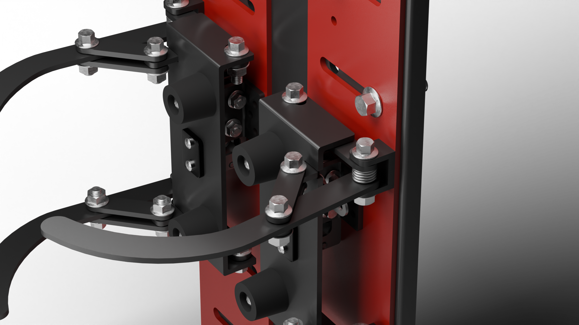
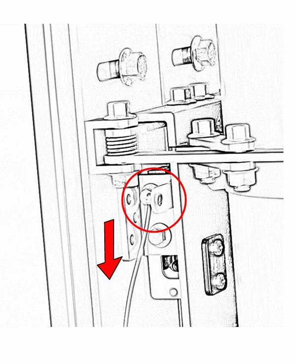
3) Locking & Release: Automotive-Grade Rotary Latch + Cable Handle
- Locking: Southco R4 rotary latch + matching catch
Selected as a proven, stress-tested component suitable for repeated cycles and vibration environments. - Release: seat pull-handle + cable
Optimised for gross-motor actuation in PPE and fast egress scenarios.
Manual override access is retained (client requirement) so the mechanism is still serviceable if cable actuation is compromised.
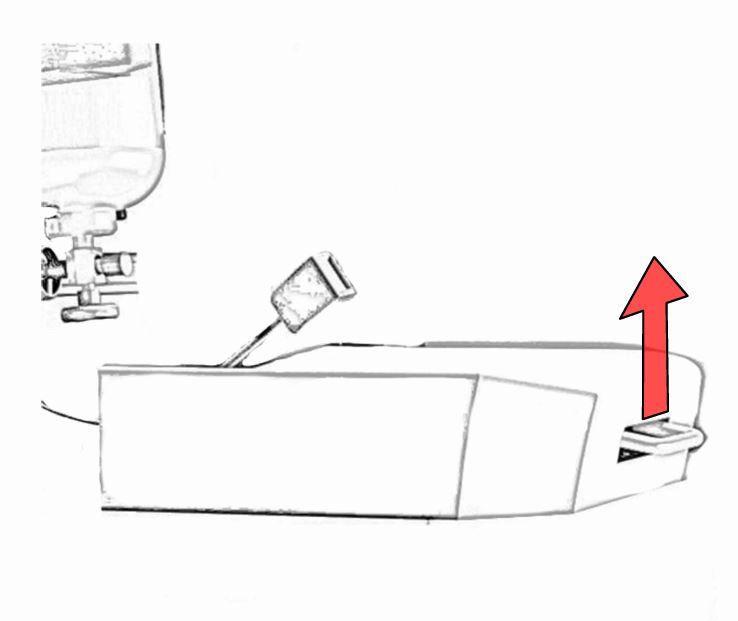
4) Vertical Restraints: Spigot + Top Stopper
Side clamping handles lateral control — but vehicle motion introduces vertical events (bumps/kerbs/braking pitch).
MP1 therefore uses two vertical controls:
- Bottom spigot carries static weight and locates the cylinder base
- Top stopper (L-bracket + elastomer bumper) prevents upward “bounce” and keeps the cylinder crown captured
Materials & Finish
- Structure: 3 mm mild steel sheet (E1 standard stock)
→ strong, cost-effective, and aligned to E1’s in-house laser + brake press capability - Fasteners & springs: stainless fasteners + torsion springs sized for reliable reset
- Bumpers/contact surfaces: nylon/rubber at wear points to reduce noise, impact, and abrasion
- Finish: powder coat; red for user-actuated/moving parts to improve discoverability
Structural Performance (FEA Summary, Explained)
Global requirement: withstand 10 g crash event with ~20 kg cylinder
Equivalent test load ≈ 1962 N (used as the basis for load cases).
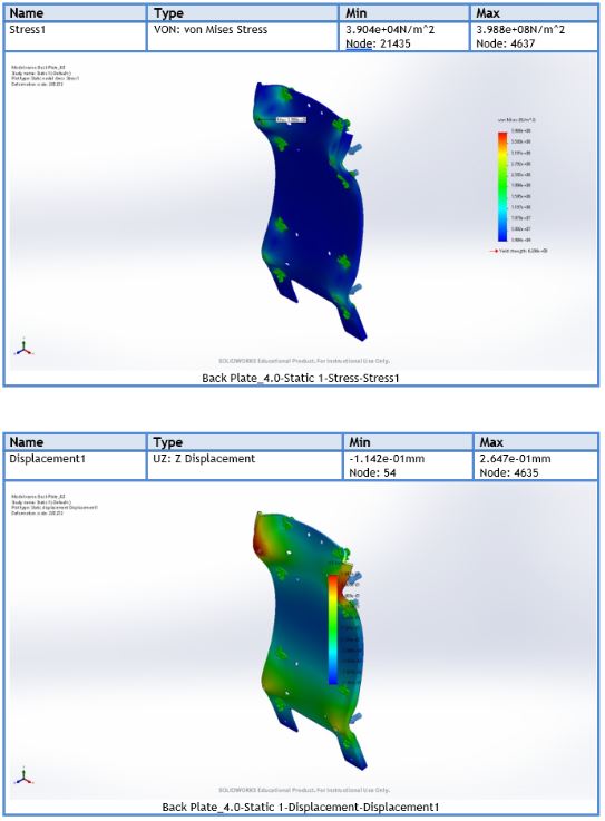
Back Plate (V4.0)
- Max stress: ≈ 398.8 MPa (below UTS 724 MPa)
- Peak deflection: ~0.26 mm
- Added formed bends reduced peak stress by ~29.7% vs a flat plate
What this means: the back plate is the primary load path into the seat structure. Introducing bends increased section stiffness (higher second moment of area), lowering peak stress and limiting movement during crash loading.
Main Body Assembly (Slide-to-Back-Plate Interface)
- Max stress: ≈ 1.533×10⁸ N/m² at the interface
- Deflection: ~0.075 mm
- Weld areas around pivot/latch brackets remain in the elastic region
What this means: the interface is where loads transition from adjustable geometry (sliders) into the main structure. Low deflection here helps maintain consistent latch engagement and reduces rattle/creep over life.
Top Stopper & Spigot
- Stopper stress: ≈ 3.94×10⁷ N/m², deflection ~0.5 mm (bump event)
- Spigot stress: ≈ 1.98×10⁶ N/m², deflection ~0.0087 mm (static weight)
What this means: the spigot is intentionally over-stiff to act as a locator and static support. The stopper is allowed some controlled compliance (via bumper/geometry) to manage vibration inputs without transferring harsh shocks into the BA set.
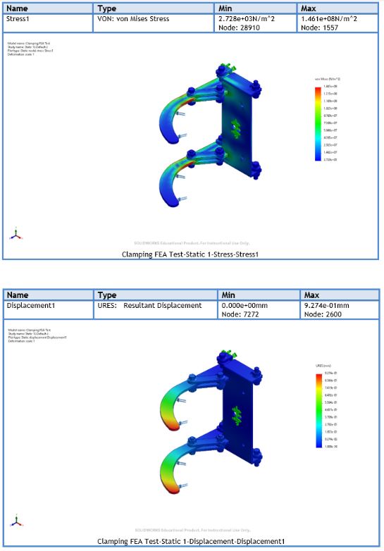
Clamping Arms
- Max stress: ≈ 1.46×10⁸ N/m² at inner curve
- Tip deflection: ~0.93 mm under 981 N (half-side load)
What this means: the arms are designed to flex slightly under load (sub-mm level) while maintaining latch engagement. The dual-link bars and latch geometry ensure the clamp stays secure even with vibration and off-axis inputs.
Fatigue Life (S–N Based)
Daily service involves repeated stow/release cycles and smaller shock events (bumps/braking). Using S–N reasoning and conservative assumptions:
- Main body: operational stress ≈ 1.533×10⁸ N/m² → life > 15 years; stresses remain below an assumed endurance limit of ~327.5 MPa (alloy steel assumption).
- Clamping mechanism: ~21,915 cycles (4 open/close per day × 15 years) → exceeds life target with only sub-mm tip deformation expected and no critical fatigue hot spots.
Manufacturing & Assembly (DfMA)
Designed to match E1’s existing fabrication workflow and minimise custom processes:
- Laser cut sheet components (repeatable, nested for material efficiency)
- Brake press bends on back plate / push plate / stopper bracket (controlled radii)
- MIG weld pivot mounts + latch brackets + link connectors (QA focus: bracket alignment)
- Powder coat (corrosion + durability + visual coding)
- Final assembly: arms + latch + springs + cable + sliders; set width; pin via pilot holes
Outcome & Value to E1
- Standardises BA stowage across different customer BA formats (single + twin-pack)
- Reduces bespoke engineering effort and simplifies quoting/build variance
- Improves in-cab usability through gross-motor interaction and clear touchpoints
- Demonstrates a verified structure for crash and service loads via FEA + fatigue reasoning
Naming/integration: aligned to E1’s convention as MP1 (Modular Pack 1), complementing SP1/SP2.