MP1, Breathing-Apparatus Stowage
A push-to-stow cradle for breathing-apparatus cylinders in fire-appliance crew cabs, designed with Emergency One as a group project and built as a 1:1 prototype.
On this page
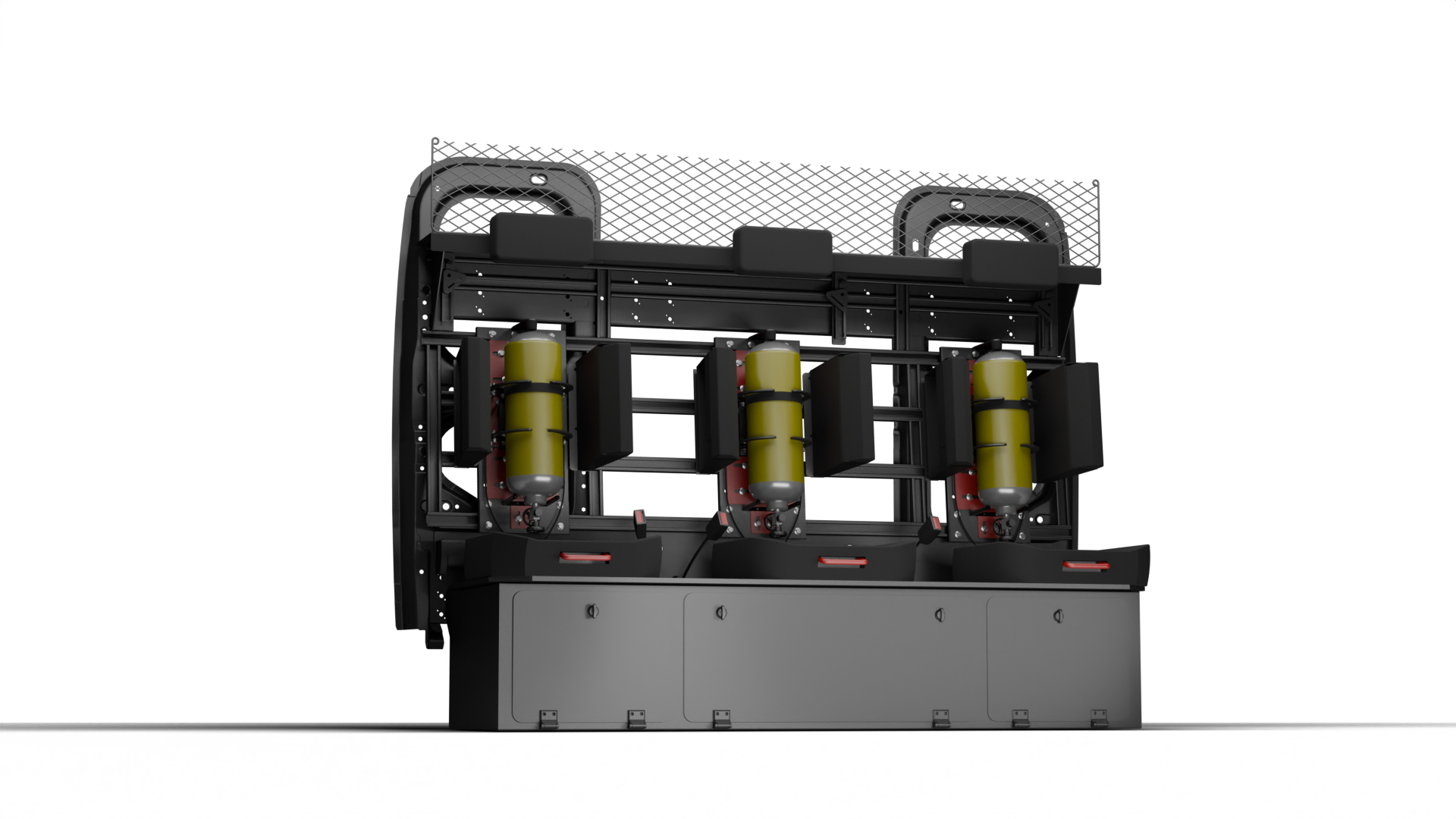
MP1 is a stowage cradle for breathing-apparatus (BA) cylinders in the crew cab of a fire appliance. We designed it with Emergency One (E1) as a four-person industrial group project at the University of Strathclyde. One adjustable assembly holds either a single cylinder or a twin pack, clamps as the cylinder is pushed in, and lets go when you pull a handle in the seat.
“We” below means the group. My part was the mechanical development: CAD modelling, the FEA, and engineering input on structure, materials and manufacturability.
The brief
Fire services are moving contaminated kit out of the crew cab and into the body of the appliance, and E1 was designing a new stowage bracket for almost every cylinder type and manufacturer. They wanted one adjustable design instead. It had to:
- fit the existing cab space without changing the vehicle structure
- take single and twin-pack formats without a unique bracket for each customer
- work with gloved hands in low visibility, with the cylinder still reachable for valve checks
- restrain a cylinder of about 20 kg in a 10 g crash, a load of about 1,962 N (20 kg × 9.81 m/s² × 10)
- last 15 years in service
- be made on E1’s own laser-cutting, press-brake and welding equipment
The operations manual we wrote gives a 35 kg maximum cylinder weight, against the 20 kg used as the analysis basis.
The space it has to fit
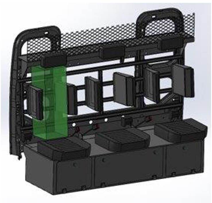
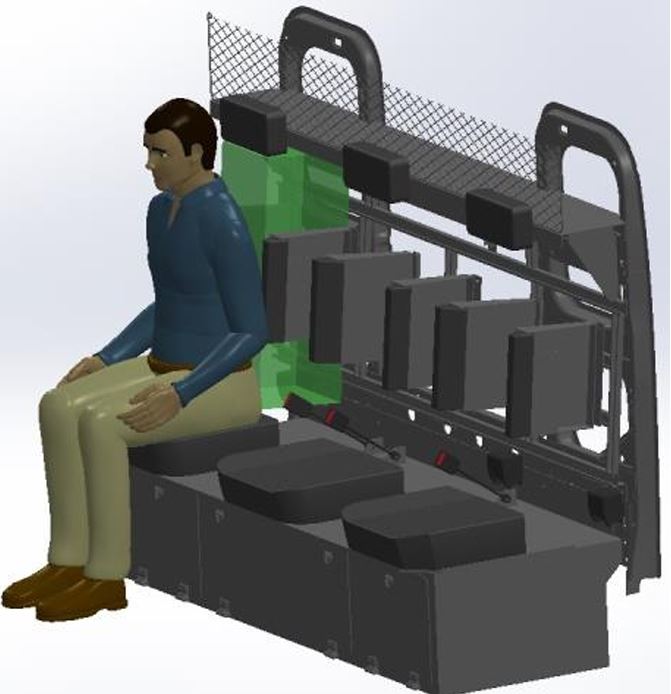
The envelope came from E1’s cab CAD, where the allowable volume behind the seat is the green zone below. It is 256 mm wide, 735 mm high and 275 mm deep. Taking it straight from the cab model meant the design could be installed without redesigning the cab, and the same logic should carry over to rear lockers. Depth is the controlling constraint, because of cab comfort and clearance around the seat and controls. The operations manual lists the finished unit as 583 × 260 × 230 mm (width × height × depth), but those labels look transposed.
How it works for the firefighter
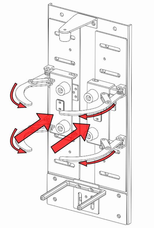
The motion is a single push to stow:
- Push the cylinder down into the dock. This is a gross-motor action.
- The push plate retracts and guides the cylinder into position.
- Curved side arms wrap around the cylinder and clamp it.
- A rotary latch locks the mechanism.
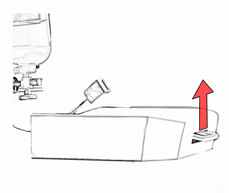
- A pull handle built into the seat releases the latch for quick removal.
The parts the user touches are red, so they stand out against the darker cab interior and aren’t lost against yellow protective gear.
Design development
Back plate and sliding panels
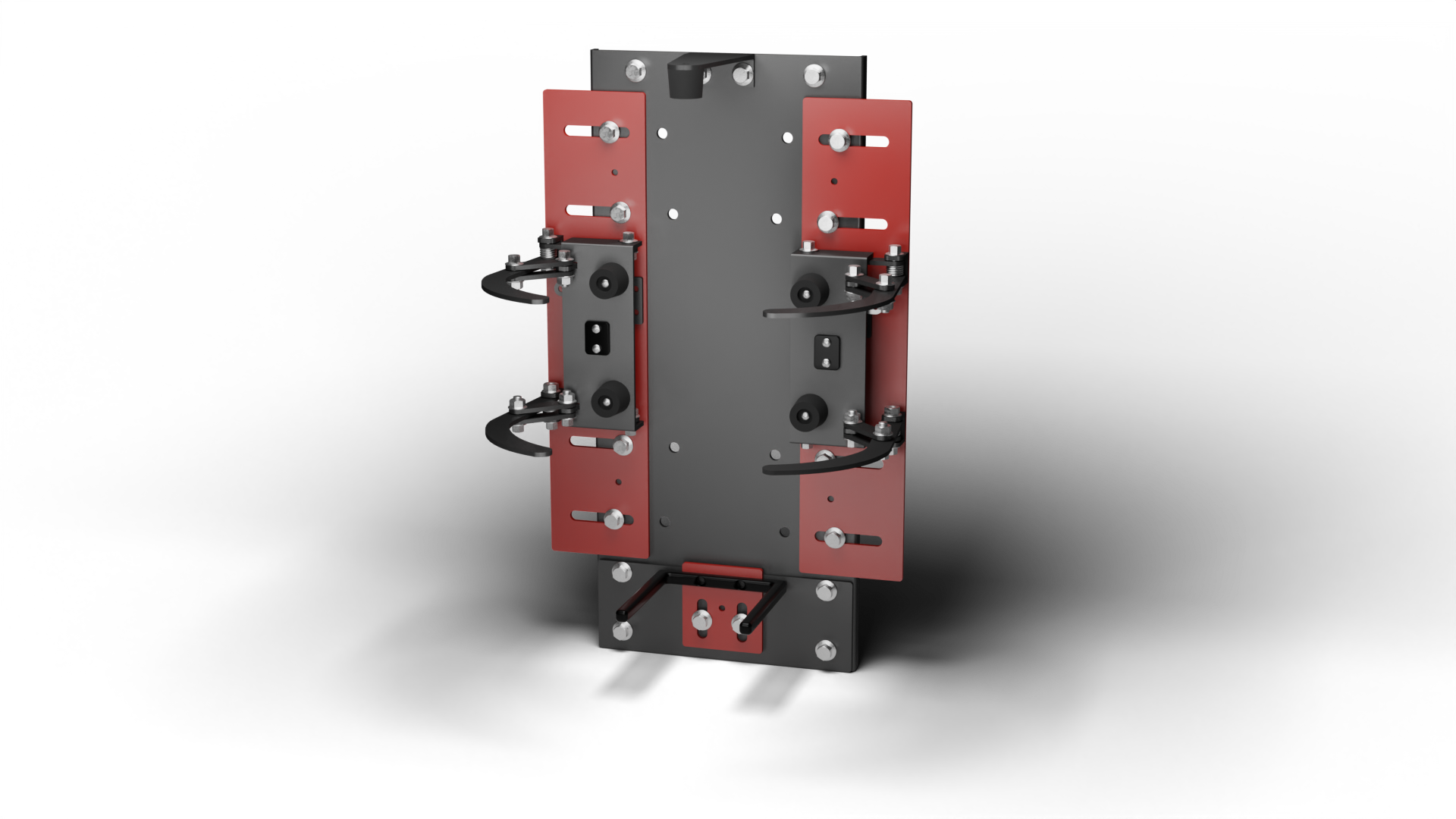
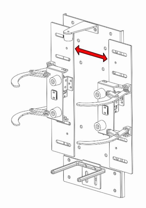
The back plate bolts into E1’s seat frame and is the main load path. Two sliding front panels set the clamping width, so one backbone takes single and twin-pack formats, and the panels can be pinned through pilot holes to stop them drifting. The operations manual gives an adjustment range of 150 to 250 mm in width and 450 to 500 mm in height.
The plate went through five versions. The first split it into a rear plate and two sliding panels. Later versions simplified the panels to plain rectangles, which cut manufacturing complexity and stress concentrations, and added mounting points. In the last version we added formed bends to the rear plate, because E1 pointed out that a flat plate would be prone to buckling, and pilot holes in the sliding parts, because slotted adjusters tend to shift under load. In the FEA the bends cut the peak stress by about 30% compared with the flat plate.
Clamping mechanism
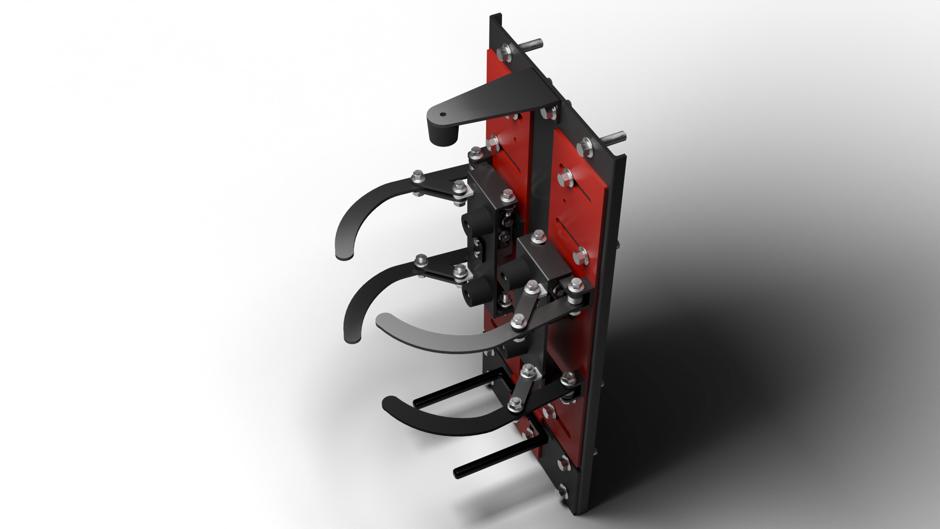
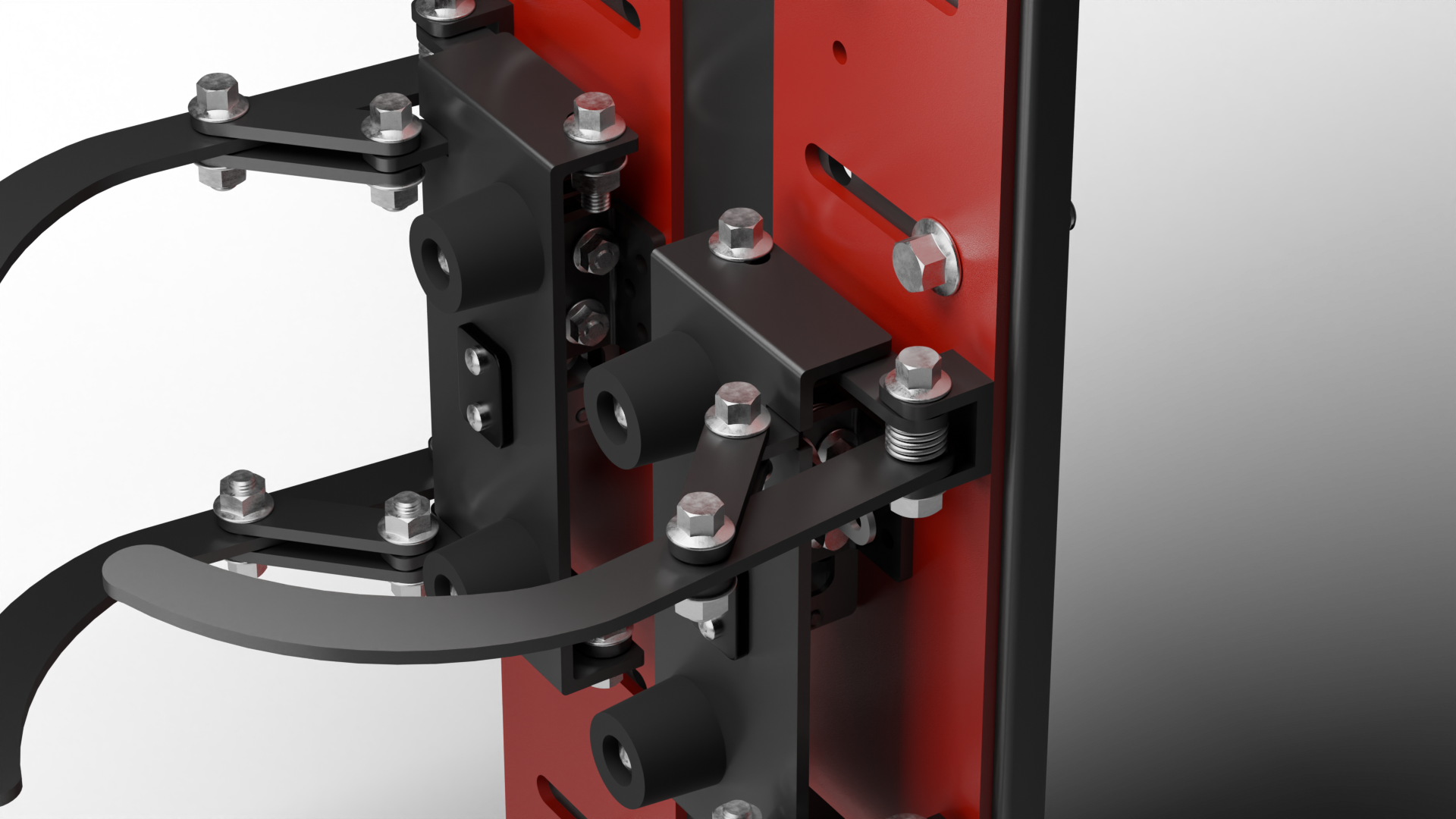
The clamp was the hardest part of the design. The first version was a two-bar linkage with trigger plates. It put most of the load through one bolt, the plates rattled because nothing constrained them from behind, and nothing stopped the cylinder lifting. A top stopper fixed the vertical restraint. A scissor mechanism then steadied the plates, but E1 warned that it would be prone to seizing under vibration in such a tight space. The final version dropped the scissor and its spindle. Each arm pivots on a single bolt and is driven by two link bars, which cut the part count and spread the load that the FEA had shown going through the old connectors. Torsion springs return the arms to open after release.
The aim throughout was for clamp loads to be reacted into the back plate and seat frame rather than into plastics or trim.
Locking and release
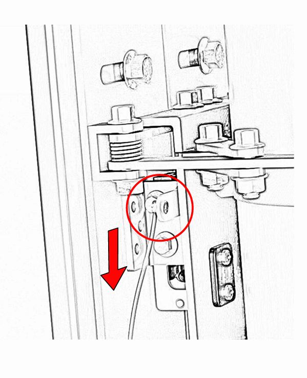
After trying E1’s existing systems and commercial alternatives, we preferred a release handle built into the seat, between the user’s legs, over the usual handle at shoulder height. The lock is a Southco R4 rotary latch with its matching catch, a part E1 already uses and recommended for repeated cycles and vibration. The handle pulls the latch through a cable.
E1 asked for a manual override in case the cable fails. The design keeps access to the latch for that, although the report notes it could be made easier to reach.
Vertical restraint
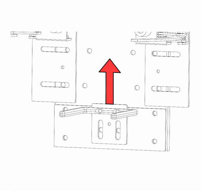
Side clamping controls lateral movement, but vehicle motion also gives vertical events from bumps, kerbs and braking pitch. A bottom spigot carries the static weight and locates the cylinder base, and its height can be adjusted. A top stopper, made from an L-bracket with an elastomer bumper, prevents upward bounce and keeps the cylinder crown captured.
Materials and finish
The structure is mild steel sheet, which is E1’s standard stock and suits their laser and press-brake capability. The report’s material selection gives 3 mm sheet, while its costing and manufacturing steps and the operations manual use 4 mm. Fasteners and springs are stainless steel, with nylon and rubber at wear points and stops. The parts are coated black, with red for user-actuated and moving parts.
Structural analysis
We ran linear static FEA in SolidWorks on the main components, using the 10 g, 20 kg basis of 1,962 N.
| Component | Load in the report text | Peak von Mises stress | Peak displacement | Notes |
|---|---|---|---|---|
| Back plate (V4.0) | 1,962 N on the eight slide-plate fixings (the saved study says 2,000 kgf, about 19.6 kN) | 398.8 MPa | 0.26 mm | Formed bends cut the peak by about 30% against a flat plate |
| Main body, slide plates to back plate | 1,962 N across the pivot and latch mounts | 153.3 MPa | 0.075 mm | Welds around the pivot and latch brackets stay intact |
| Clamping arms | 981 N across the inside faces (the saved study says 1,000 N) | 146 MPa | 0.93 mm at the tip | Peak at the inner curve; led to two link bars per arm |
| Top stopper | 50 N upward, deliberately exaggerated for a bump | 39.4 MPa | 0.5 mm | Some controlled compliance is intended |
| Spigot | 196.2 N, the cylinder’s weight | 1.98 MPa | 0.0087 mm | Static weight; intentionally stiff |
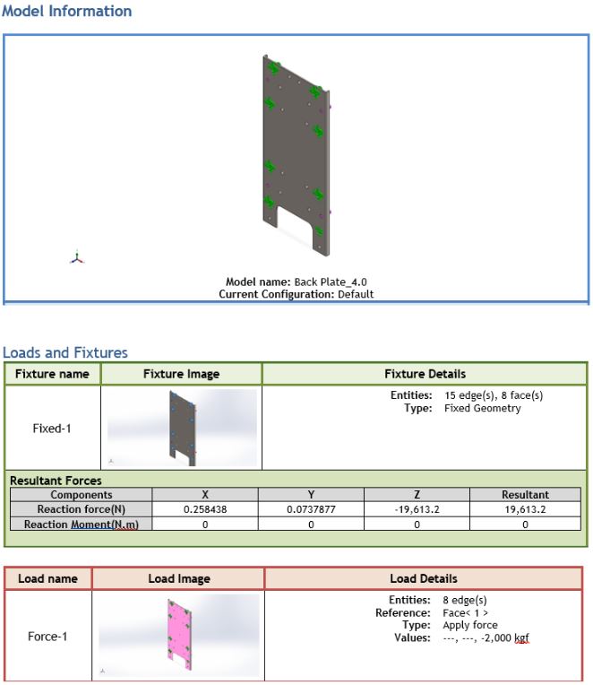
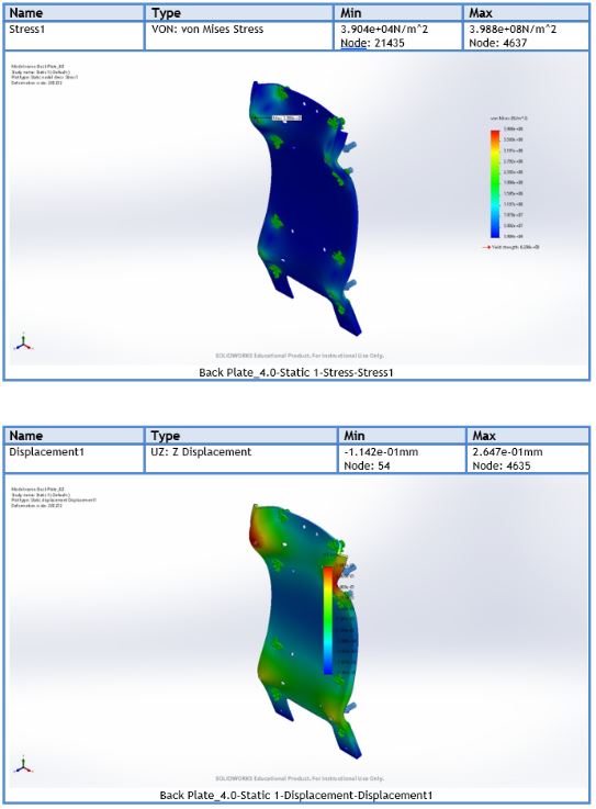
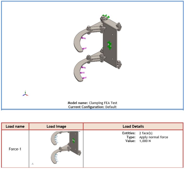
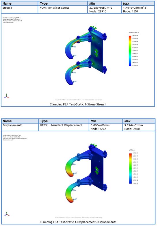
Two inputs need care. The saved back-plate study applied 2,000 kgf, a reaction of 19.6 kN, which is ten times the 1,962 N in the report text. It may have been a deliberately severe case or an entry error. The 398.8 MPa is the stress at that load. The analysis is linear, so at 1,962 N it would be about a tenth of that, but the study hasn’t been re-run. The studies also used alloy-steel properties: the plots mark a yield strength of about 620 MPa and the report compares the plate stress with a tensile strength of 724 MPa. The sheet is mild steel, which has a lower yield strength, so the results need re-running with the actual material. Peak stresses at fixings and corners can also be modelling artefacts.
For fatigue we built an S–N curve for alloy steel from a tensile strength of 655 MPa, taking the endurance limit as half of that (327.5 MPa) and the stress at 10³ cycles as 90% of it, and applied fully reversed loading. Daily use was taken as eight bump events and four braking events on the main body, and four clamp cycles a day on the mechanism, for 15 years (21,915 clamp cycles). Both were predicted to outlast 15 years, with arm-tip deformation under 1 mm. The stresses used were the crash-load stresses, which are higher than everyday ones, but the curve is an estimate from a rule of thumb, so this is a plausibility check rather than a validated fatigue life.
Prototyping
We first built a model from laser-cut acrylic and 3D prints to check the four-bar linkage and the sliding panels against each other before committing to metal. It exposed clashes and misalignments that the CAD hadn’t.
We then made a 1:1 functional prototype from laser-cut, press-brake-formed mild steel, with springs for the clamping action and TPU dampers for high loads, finished in paint. It was completed after the Stage 2 report was submitted. As a proof of concept it showed the push-to-stow action and the geometry working; the clamp linkage was the least refined part and the one I would simplify first.
The design was shaped around E1’s fabrication workflow so that it needs no special processes:
- Laser cut the sheet components, nested six units to a sheet.
- Brake press the bends on the back plate, push plate and stopper bracket.
- MIG weld the pivot mounts, latch brackets and link connectors.
- Powder coat for corrosion resistance and the red visual coding.
- Assemble the arms, latch, springs, cable and sliders, set the width and pin it through the pilot holes.
Outcome
The group delivered a design report, concept studies, a detail drawing pack, the prototype, a production-style operations manual and an advertisement pack. E1 reviewed the design at several points, and their feedback shaped it, from the sheet sizes to the latch and the clamp linkage. The costing, which adds estimated laser-cutting, bending, welding and coating costs to material, came to about £181 a unit before a 20% margin. The design follows E1’s naming as MP1 (Modular Pack 1), alongside their SP1 and SP2.
The prototype is a functional demonstrator rather than a qualified product. It hasn’t been crash-tested or fatigue-tested, so the 10 g result rests on the analysis above, and it isn’t certified.
Further development
The report lists the next steps: crash testing, user trials with firefighters, testing the adjustment range with a wider range of cylinder types before calling it universal, and a more polished prototype. I would add simplifying the clamp linkage, making the manual override easier to reach, and re-running the back-plate analysis at the intended load with mild-steel properties.
Documents
- MP1 Operations Manual (PDF, 8 pages)
- MP1 Advertisement Pack (PDF, 6 pages)
Both were written for the project. The advertisement pack’s price and the manual’s 12-month warranty are part of that exercise.
Technical review: